C1 Race Car Build Notes
These notes are provided, not as instructions, but as guidance following the experience we had building the first 2 cars. These notes will change as we get your feedback and experiences.
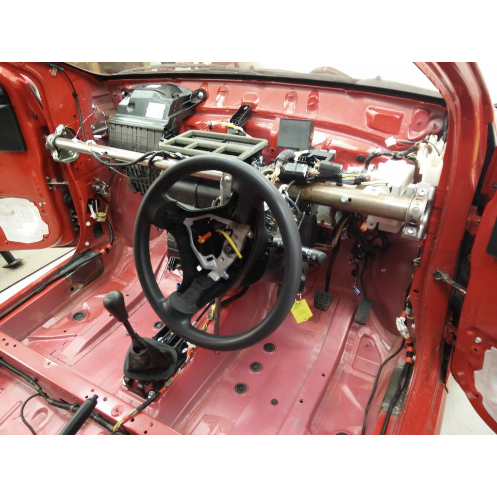
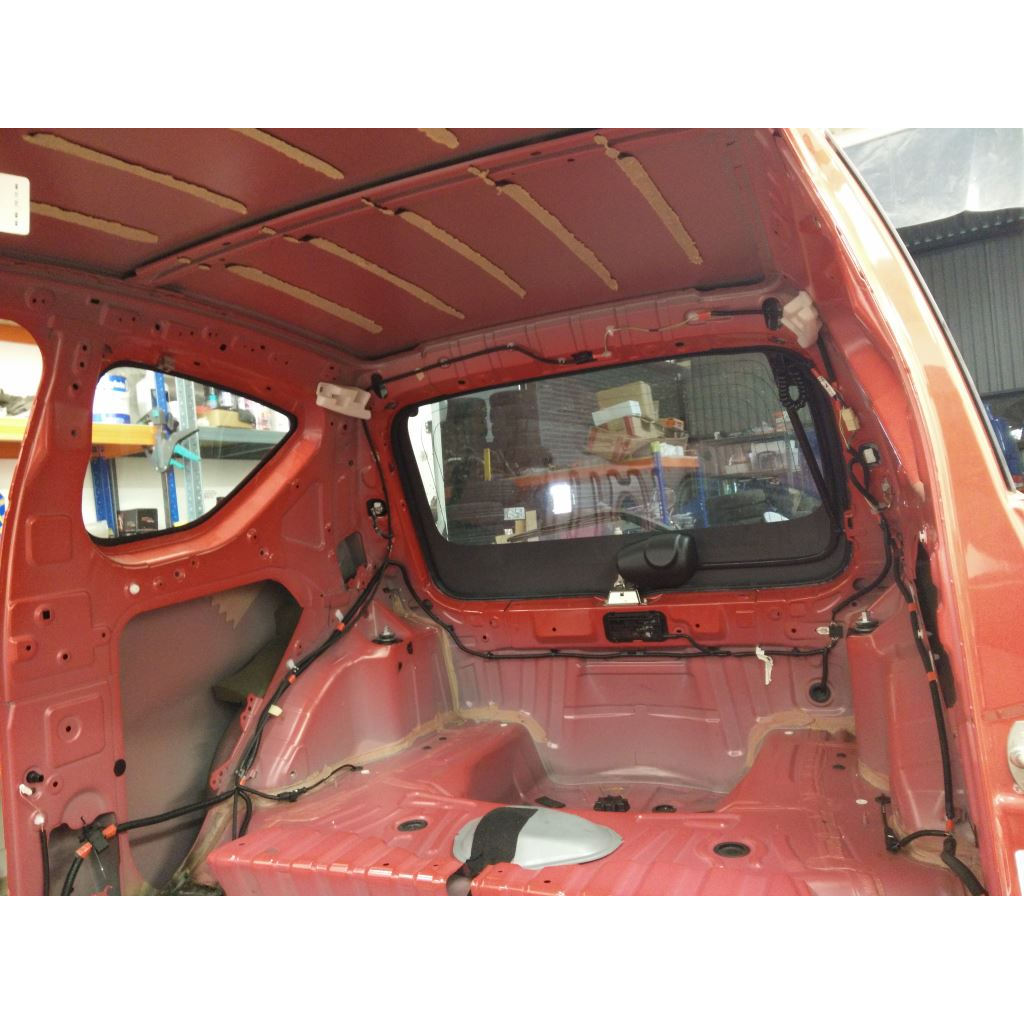
Strip the interior
You’ll need to remove pretty much all the interior trim. You must keep the following panels because they must be re-fitted once the cage has been installed:
- Both door card panels
- Both window winders (handles or switches)
- Handbrake cover
- Centre console
- Upper and lower dash panels
- Radio
- Roof aerial
The Haynes manual covers interior trim removal pretty well. Care is needed when removing the roof lining. When cutting through it with a knife make sure the tip of the knife blade doesn’t touch the steel roof panel – it will make a linear dent in it that won’t come out. Don’t just yank the roof lining – you may concave the roof panel.
Roll cage installation
Follow the Safety Devices installation instructions.
It’s a good idea to have a bag of M10 plain nuts handy so you don’t have to wind the supplied Nyloc nuts on and off the bolts as you’re dry fitting the cage – it goes in and out at least 3 times. The basic installation is as follows:
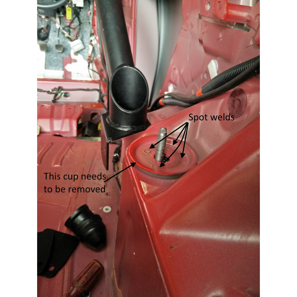
- Remove rear suspension turret flanges.
- Dry fit cage to get the positions of the foot plates.
- Drill rear suspension turrets for harness bar bolts.
- Remove cage and drill 25mm dia holes for foot plate nuts into cills. Remove paint around cage feet ready for welding.
- Dry fit cage and tack weld feet in correct position.
- Remove cage and weld (TIG if you can) feet into position.
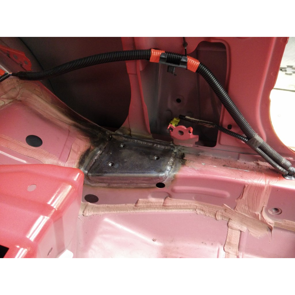
- Weld racing harness reinforcing plates into floor.
- Paint cage feet and harness plates (or the whole interior).
- Trim upper and lower dash panels to fit around front cage legs.
- Install cage using Nyloc nuts and torque as specified.
You may need to have either a Porta-Power or bottle jack when fitting the cage. People have needed to push the rear cage feet out to fit snuggly to the cills and to push the rear suspension towers apart to get the harness bar between them.
Don’t forget to fit the supplied harness bar spreader plates to the outside of the body. They’re easier to do if the rear springs aren’t fitted, so plan to do the rear springs/shock absorbers at the same time.
Detailed roll cage installation notes can be found here.
Wishbones and Driveshafts
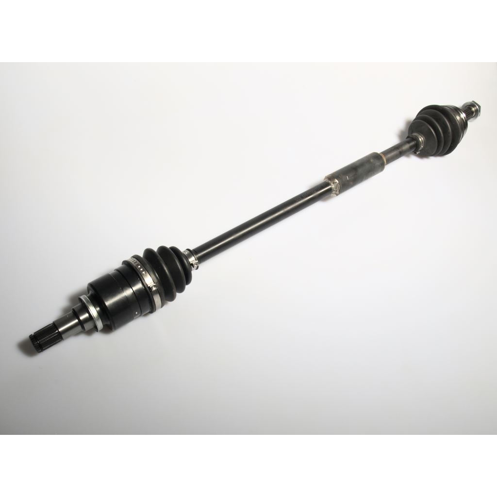
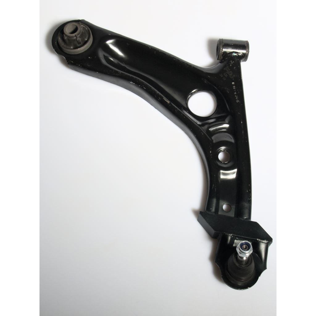
The club supplied wishbones must be fitted with our extended driveshafts. Installation sequence is as follows:
- Drain gearbox oil.
- Remove original wishbones and drive shafts. Be careful not to damage the drive shaft seals in the transmission housing.
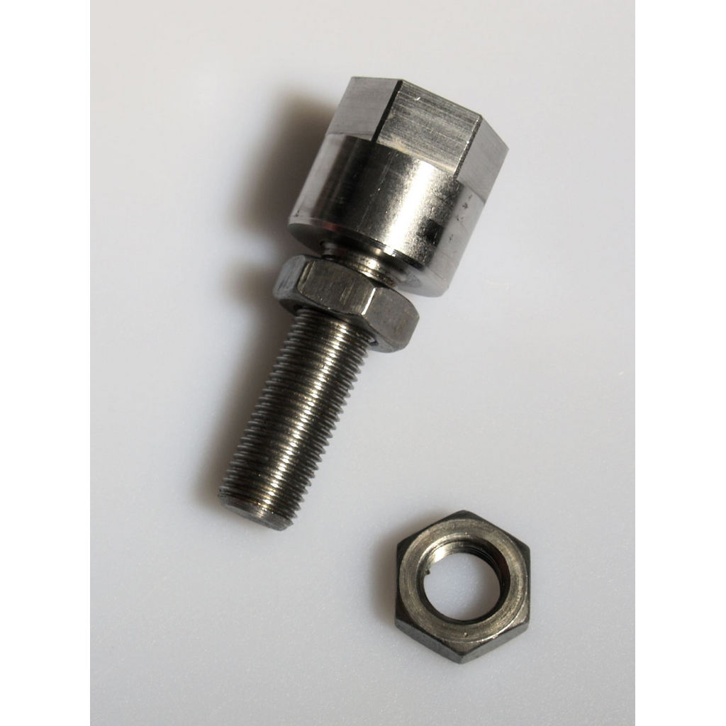
- Remove track rod adjuster and original lock nut. Screw supplied thin lock nut fully onto track rod thread. Shorten track rod leaving 18mm of thread from lock nut to outer end of track rod. A disk grinder with 1mm wide blade is the best tool for this. Remove lock nut.
- Degrease track rod threads, 2 thin lock nuts and track rod extender internal thread. Screw thin lock nut onto track rod until it is 10 mm from fully on. Apply Loctite Stud Lock to the track rod thread in front of and behind the thin lock nut. Screw the thin lock nut full on. Screw on the track rod extender until it is fully on and lock the lock nut against the extender. We want the extender to be a permanent part of the track rod.
- You MUST check you have KYB dampers (see regs)
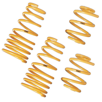
- If you’re fitting lowering springs, remove the standard spring and replace with the lowering spring.
- Fit the extended drive shafts into the gearbox, being careful not to damage the seals. Take care of the cup on the drive shaft as a seal runs inside it.
- Fit the new club supplied extended wishbones. Torque the front pivot and rear mounting bolts to 100Nm.
- Position the end of the drive shaft into the hub and then locate the wishbone ball joint taper into the hub. Fit the ball joint nut and torque to 98Nm.
- Fit the drive shaft hub nut, torque to 216Nm and stake into the slot provided.
Fuel tank guard
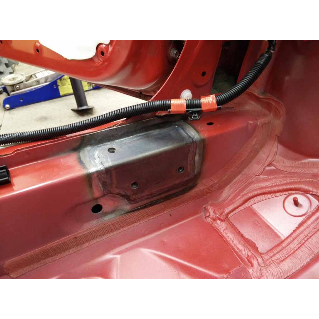
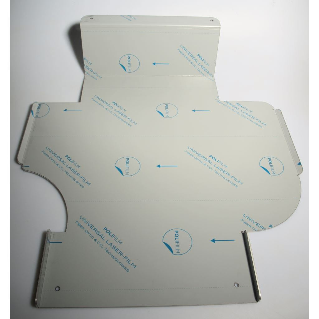
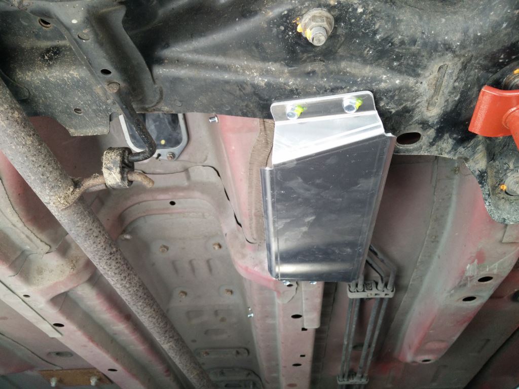
Position the guard so that it straddles the longitudinal rails. You may need to trim the seam sealer and possibly dress the flanges out to fit over the rails. The rear flange should snug up against the front spare wheel well bung, but not cover any of it.
Drill 2 x 6.3mm holes through the wheel well using the bolt holes in the guard as a guide. Attach guard with the supplied 2 x M6 button head screws and penny washers and Nyloc nuts.
Drill 2 x 3.5mm holes into the longitudinal rails using the guard as a guide and fasten guard to rails with supplied self tapping bolts.
Brake and fuel pipe guard
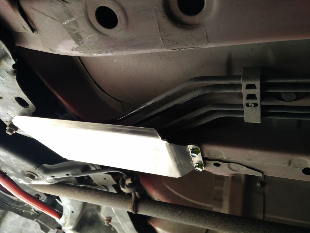
Position the guard so that it covers the brake and fuel pipes as they exit the engine bay just behind the front subframe. The front of the guard is attached to the front subframe with 2 x 6mm self tappers, the rear is screwed to the longitudinal chassis stiffener with 2 x 6mm self tappers.
To fit, mark the first hole carefully and drill 4.8mm. Fit the guard in place with the screw and then drill the other 3 holes using the guard as a guide. Install the 3 remaining screws. Go have a beer.
Lowering springs
An easy job – the most difficult part is removing the front struts. The rears can be done without removing the rear beam or hubs, although if you are going to add some camber by fitting 2mm shims between the bottom 2 hub to beam bolts, then do it at the same time.
To remove the front strut you’ll need a tool to prise the strut clamp apart. An M12 bolt filed to a profile works quite well.
Fire extinguisher
Follow the manufacturers instructions.
The only location for the cylinder is in behind the passenger seat area, See regualtion 5.3.2. At some point you will need to fit a ballast tray or passenger seat, so make sure the fire extinguisher doesn’t prevent these being fitted.
Rear fog light
There isn’t really any where a central MSA compliant rain light can be fitted, but you are allowed to fit 2 rain lights, one on each side of the car. The reversing light can be used for the left hand light and the standard fog light used for the right hand light.
To convert the reversing light, you have to either fit a red lamp cover identical to the fog light one (the best solution) or fit a red lamp. The red lamps usually show a pink light.
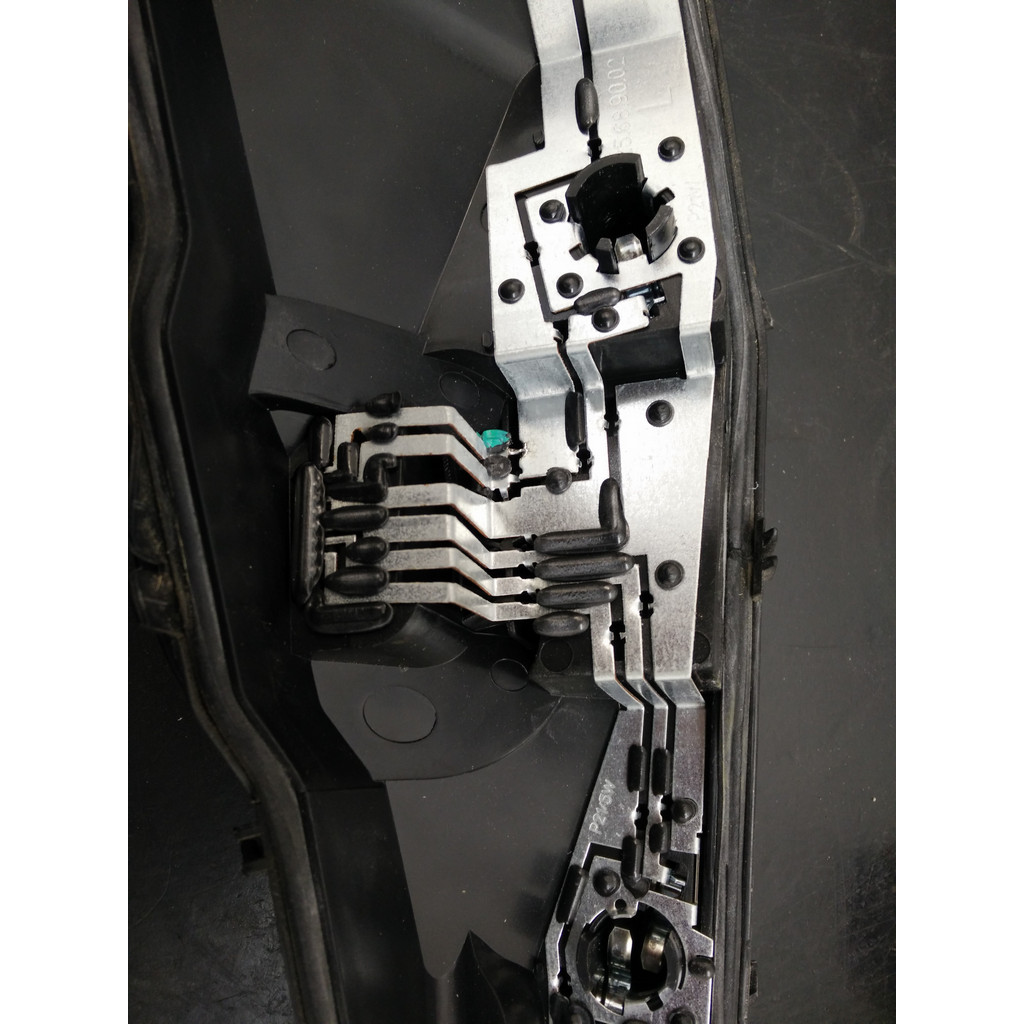
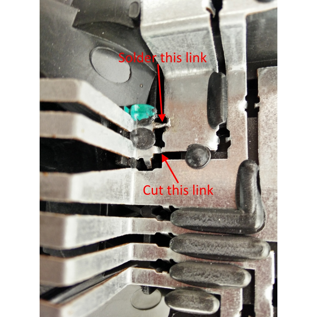
To make the reversing light come on when the rear fog light is activated can be done by adding a link wire, or by modifying the tracks in the light unit (the easiest and neatest solution). See the photos opposite.
Master switch
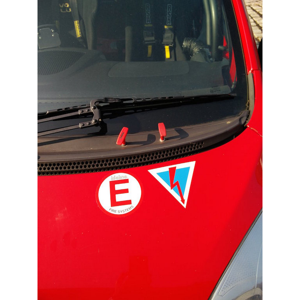
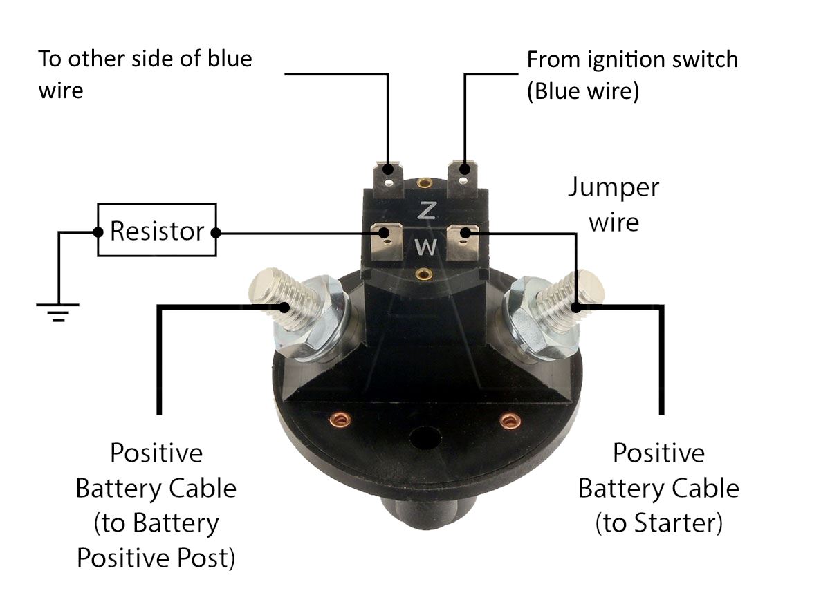
The master switch must kill the engine and isolate the battery when turned off and must be operated by the driver when strapped into the seat and from an external point that a marshal can reach easily.
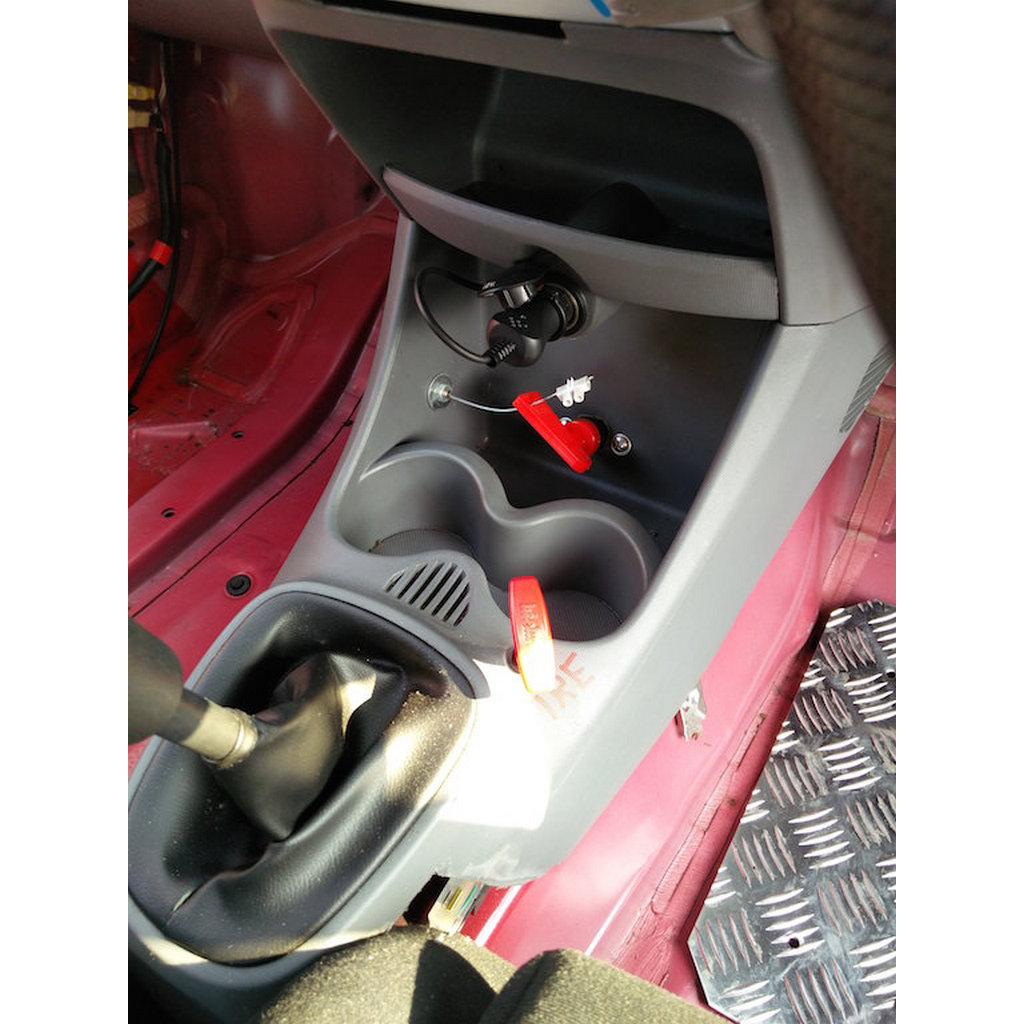
Mount the switch where it can be reached by the driver and where you can attach the pull cable. The centre console is a good place.
Disconnect the 2 big cables from the battery +ve terminal and run a battery cable from the +ve battery terminal, through the bulkhead to the switch. Run another battery cable from the switch, through the bulkhead to the 2 cables you disconnected. Make sure you use grommets if you drill new holes in the bulkhead and insulate the connection to the 2 big cables. This isolates the battery.
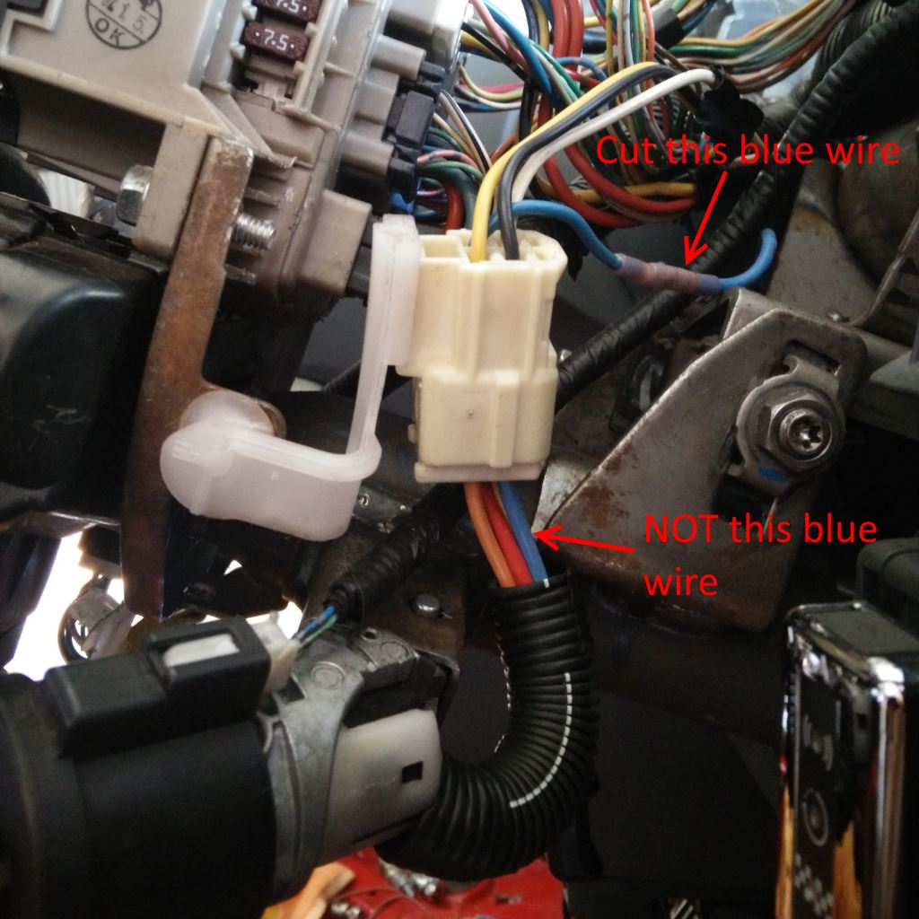
To kill the engine you will need to break into the ignition wire (blue wire coming out of the connector just above the ignition switch – see the photo on the left) and run 2 x 1.5mm wires to the terminals on the back of the switch.
Left hand drive cars
On left hand drive cars the wires coming out of the connector above the ignition switch follow the colours going in to it. Consequently you need to cut the red wire coming out of the connector just above the ignition switch on a left hand drive car.
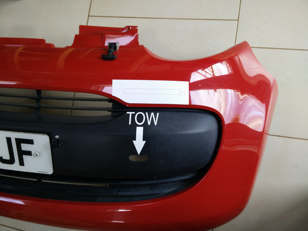
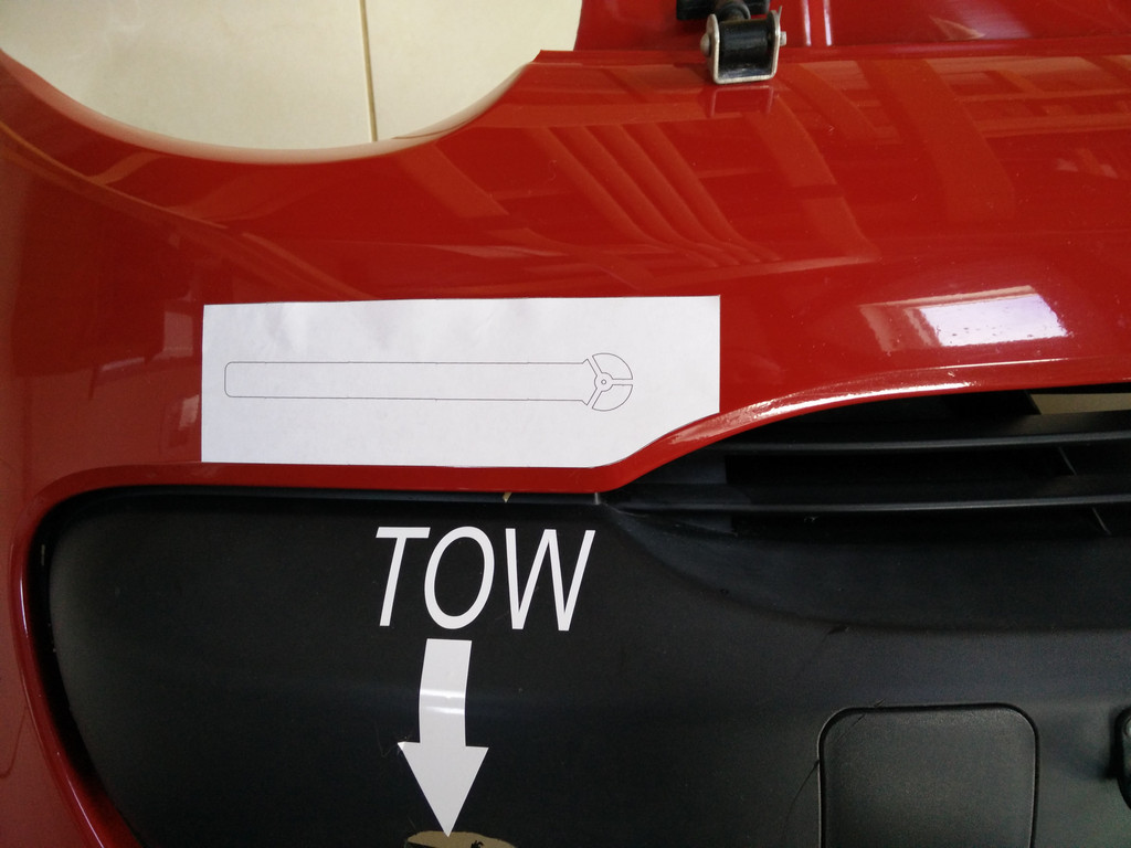
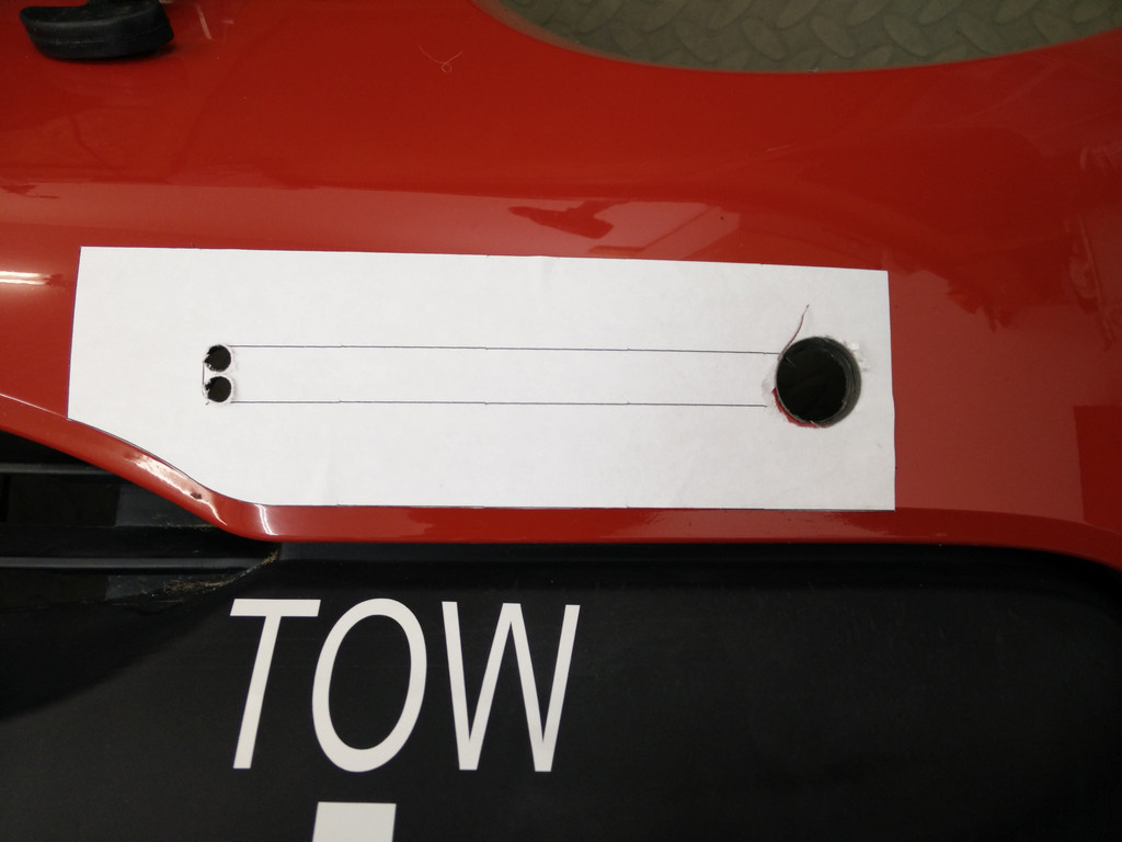
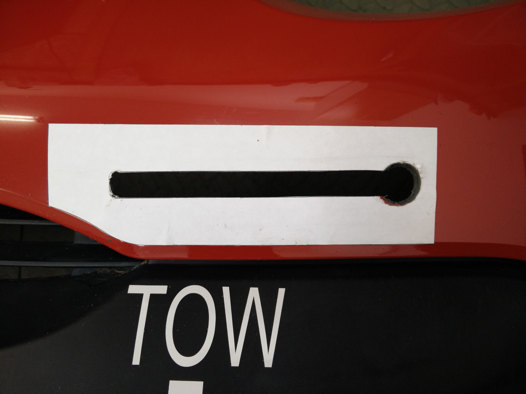
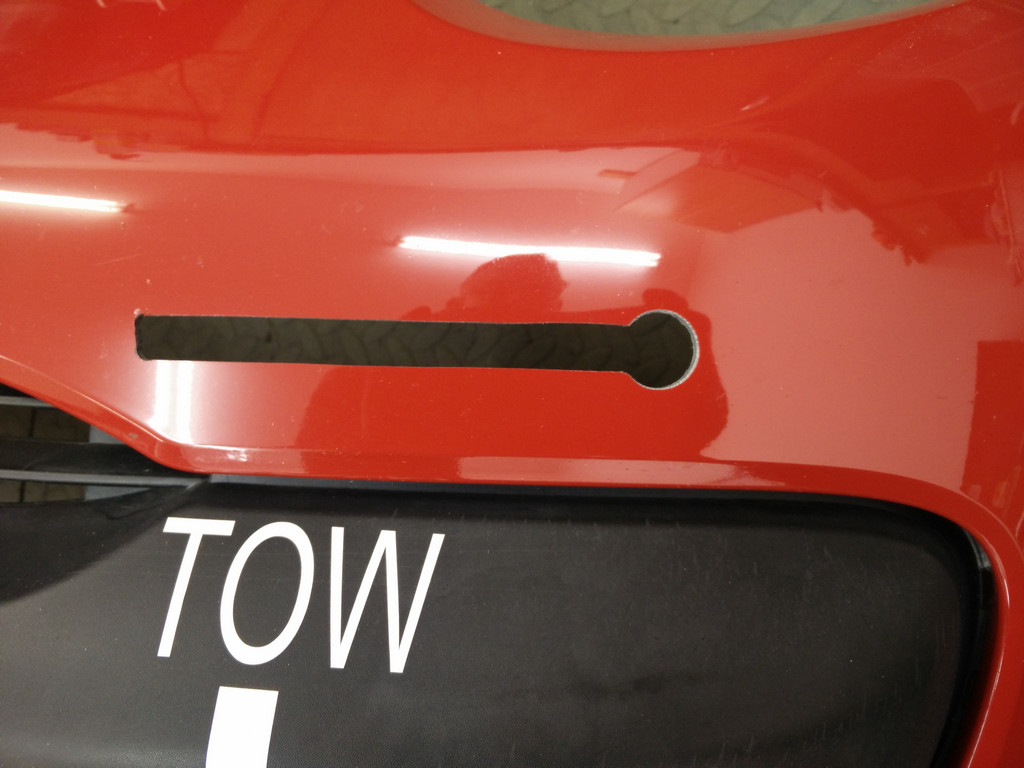
Slotting bumper for light brackets
The spot light brackets are mounted using the front crash beam mounting points. For cars up to 2010 spacers and longer bolts are supplied in the club kit. If you have a later car, you will need to make some longer spacers and buy longer bolts. Full instructions are here.
The paper template for early cars (2005-2009) can be printed from this file.
The paper template for later cars (2009-2014) can be printed from this file.
Spot Light Wiring
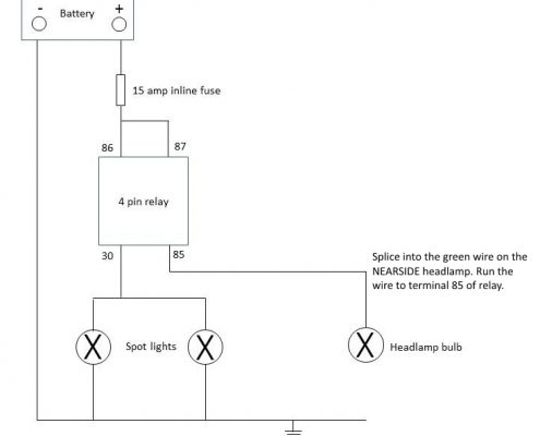
Spot lights must be wired so they conform to the regulations which say:
The spot lights will be fed from a fused relay that is operated by an input from the main beam light wires behind the left hand side headlight unit. The spot lights will activate at the same time as the standard main beam bulbs and no additional or independent operation is permitted. Additional internal switches are not allowed.
See the wiring diagram opposite (kindly created by Clive Brookson).
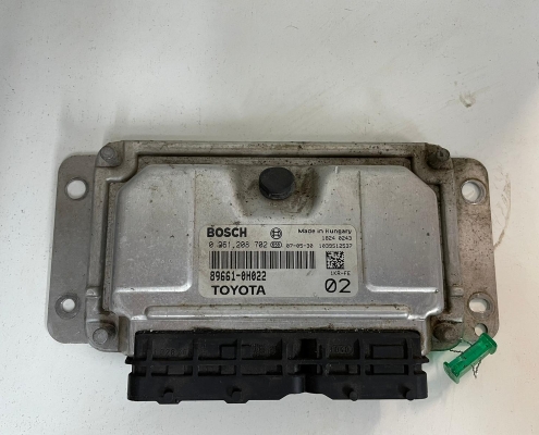
Club ECU Remapping
Your ECU must be programmed with the club map.
To have your ECU remapped at a cost of £85 please send your ECU to Sam Weller at the following address:
Hybrid Tune LTD
Renvale Technology Park
Eye Road,
Brome,
Eye
IP23 8AS
Please put your name , contact details, return address and car number in the box . If you don’t have a car number please hit request car number in your My Portal under my race cars.
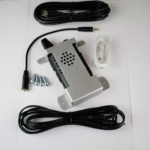
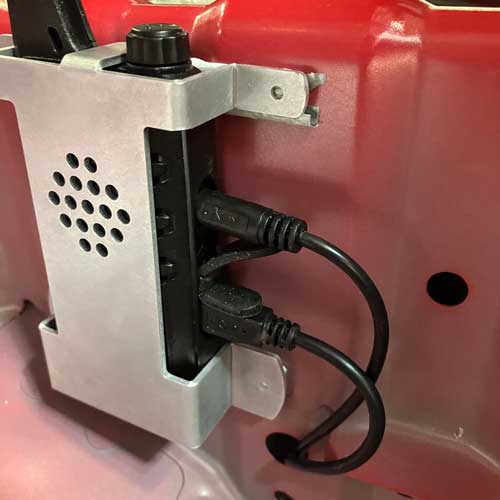
Race Receiver Fitting Instructions
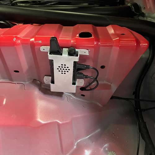
- 1 Using the supplied template carefully mark your drill holes noting the
position of the bracket in Pic 1. - 2 If you are using the supplied Rivet nuts drill 9mm holes. Set the Rivet
nuts using a setting tool and bolt the bracket and radio to the panel using
supplied button head bolts. - 3 If using nuts and bolts drill for 6mm and clearance then bolt the bracketand radio to the panel.
- 4 Plug the Headset adapter cable into the uppermost socket on the radio.
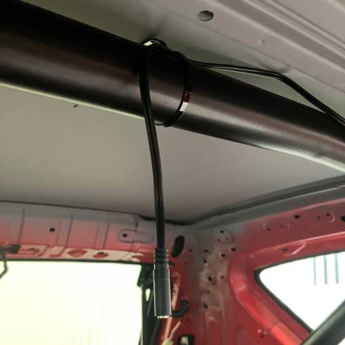
Pic 2 - 5 Plug the headset extension cable into the headset adapter cable and
route the cable through the hole in the kick panel just below and to the
right of the radio. A grommet would be advisable here. Continue the
cable run over to the roll cage and up the cage hoop to dangle approx
mid car as in Pic 3. Zip tie the cable into place. - 6 Plug the USB power cable into the small USB socket at the bottom of
the radio. See Pic 2. Route the cable through the same hole as the
headset cable and across to the foot of the rollcage then follow the
existing loom along the sill and along the centre crossmember to the
“tunnel”. Feed the cable under the crossmember and along the “tunnel
towards the front of the car. Plug the USB into a suitable USB female
power supply.
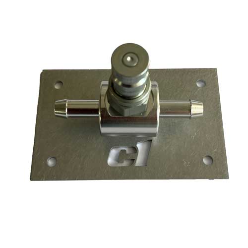
Fuel Pump Out Kit Guide
- 1. Disconnect the battery.
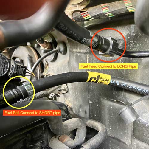
- 2. Remove the fuel pipe connecting the fuel rail to the fuel
supply pipe by squeezing the grey tabs on each
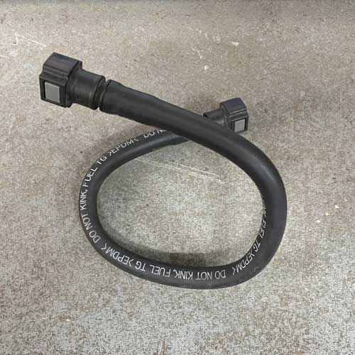
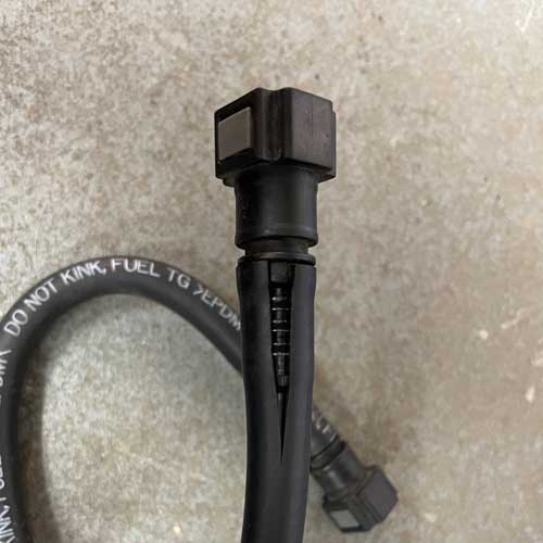
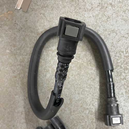
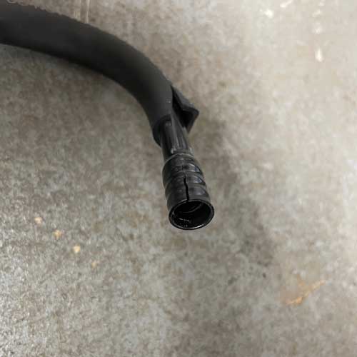
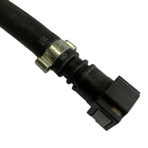
connector. Be prepared for some fuel spillage. - 3. You will now need to remove the OEM connectors from
this pipe to instal onto the new pipework. Refering to pics
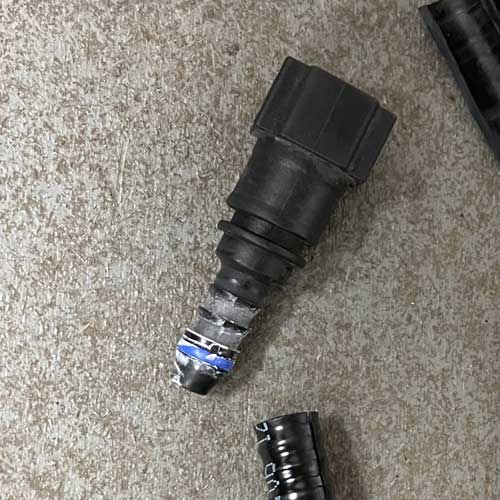
in the build notes carefully cut the soft outer fuel pipe
coating to reveal the hard plastic pipe inside. - 4. With a razor type blade VERY carefully score the hard
plastic pipe down its length and try to split the
connectors from the pipe rather than cutting all the way.
The connectors are not available after market, similar are
available but they WILL NOT FIT. - 5. Inspect your connectors to ensure they are in good
order then push one of the Oetiker clips supplied onto the
new rubber pipes on each side of the dry-break adaptor
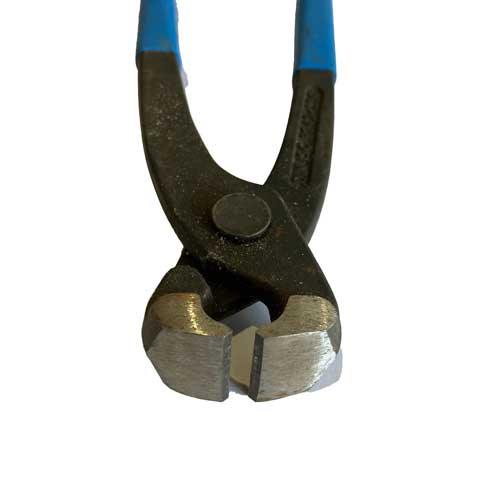
and push the connector on. Using a crimping tool, not
side cutters or pliers compress first one ear then the
other ear to clamp your hose to the connector. If you are
unfamiliar with these clips there are You tube video
tutorials. It is not difficult. - 6 You should now have the OEM connectors fitted to the
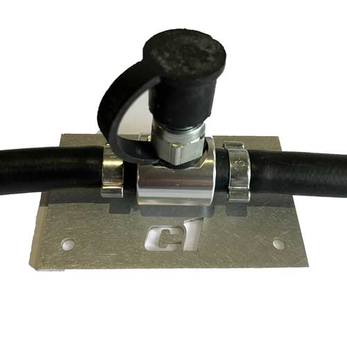
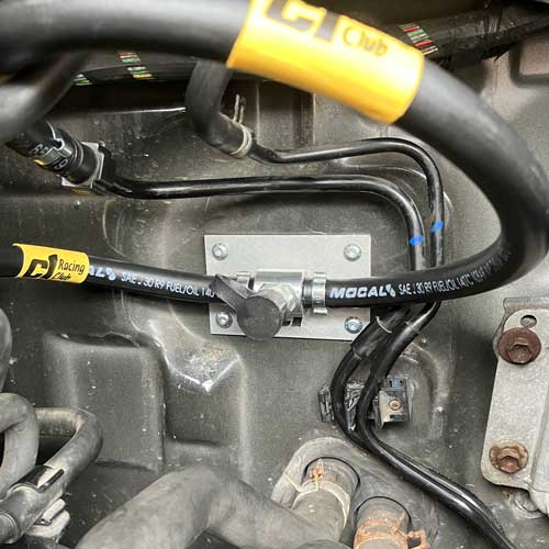
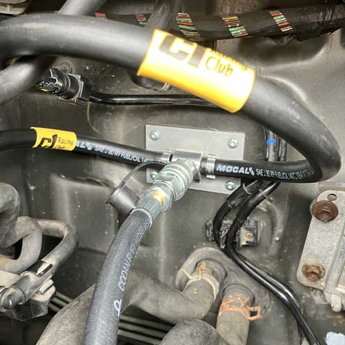
new piping ready for the next operation. - 7. Locate the flat area of bulkhead panel as shown in pics.
- 8. Decide if you are using nuts and bolts or tek screws to
mount your plate to the bulkhead, both are supplied. - 9. If you are using nuts and bolts use the mounting plate
as a template. Drill a 5mm hole through the top right hole
in the plate then fasten the plate with a nut and bolt to
hold it in place while you drill the next hole. It is fiddly,
one person inside the car and one in in the engine bay is
best way.Continue and drill the other holes. Remove the
mounting plate from the bulkhead and attach the drybreak
adaptor to it with the two countersunk screws
provided. Re-attach the plate to the bulk head ready to
make the pipe connections. - 10. If you are using Tek screws you need to first attach the
dry-break adaptor to the mounting plate with the counter
sunk screws provided then screw through the top right
hole in the mounting plate before squaring up the plate to
screw in the other fasteners. - 11. The SHORT pipe from the left hand side of the drydreak
adaptor goes to the fuel rail and the Long pipe curls
round and up to the fuel supply pipe. - 12. Reconnect the battery, turn on ignition and inspect for
fuel leaks. The Aeroquip dry-break fittings are Loctited
and should not be further tightened or disturbed unless
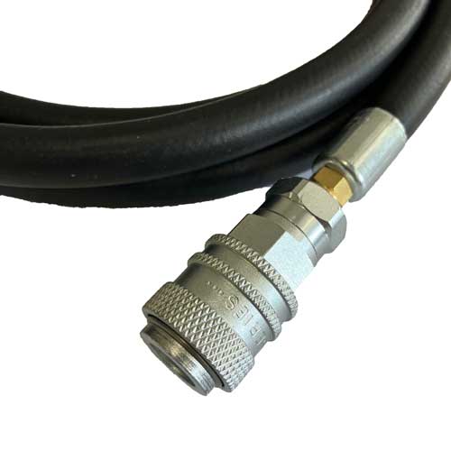
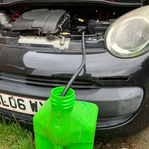
absolutely necessary. - 13. The female part of the dry-break will allow you to
safely remove fuel from under the bonnet when used in
conjunction with our pump-out wiring adaptor kit.
Fuel Pump Out Wiring Guide
- 1. DISCONNECT BATTERY
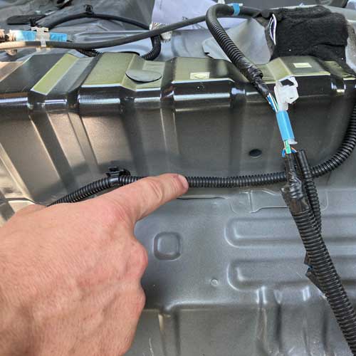
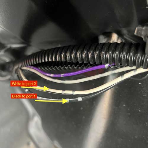
- 2. Locate fuel pump wiring behind drivers seat.
- 3. Snip zip tie part of loom clips.
- 4. Withdraw the four wires from the loom tidy.
- 5. Cut the two thick wires (one is black one is white)
midway between the loom clips. - 6. Gather the black and white wires together and
push the supplied heat shrink tube down the wires to
the loom protector. - 7. Push the cut wires on the left through the boot as
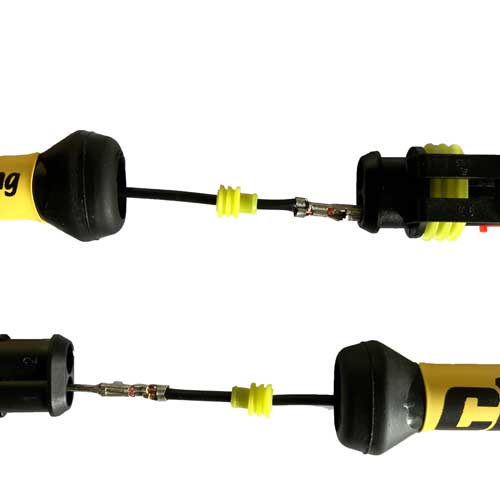
far back as you can, repeat for wires on the right. - 8. Push a yellow grommet onto each of the four wires
back to the rubber boots. - 9. Cut back 5mm of insulation on each wire.
- 10. Crimp on a female connector to each wire on the
LEFT. - 11. Crimp on a male connector to each wire on the
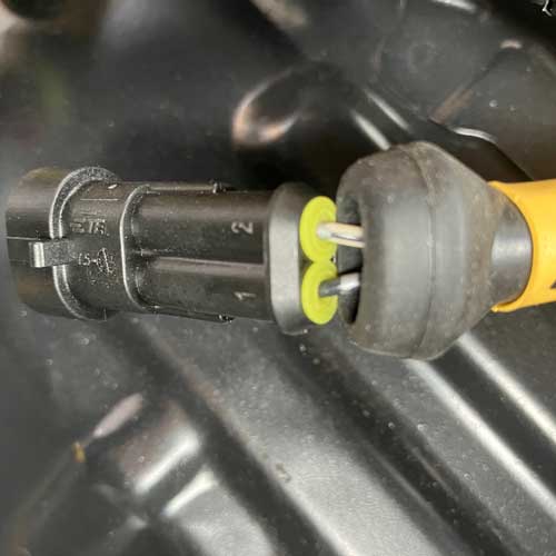
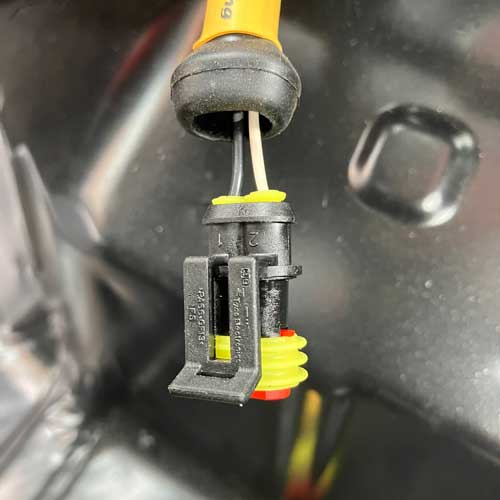
RIGHT. - 12. The connector housing ports are numbered 1 and
- 2, push the female connectors into the housing with
the yellow seal and red locating clip. Black wire goes
to port 1, white to port 2 the connectors will click
when they are home. Then push the red locating clip
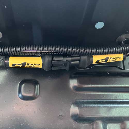
inwards to its stop. - 13. Push the male connectors into the long black
housing again black to port 1 white to port 2 until they
click home. - 14. Test wiring now, push housings together reconnect
battery, turn on ignition and listen for 2 second pump
prime, then start engine. - 15. All should be working!
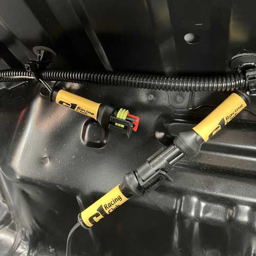
- 16. Turn off ignition and separate the super-seal
housings, now plug the supplied auxiliary wire into the
cigarette lighter socket and into the super-seal plug
that goes to the pump, turn on ignition one click and
listen for pump to prime. - 17. All should be working!
- 18. Now push the little yellow grommets up the wires
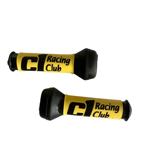
into the super-seal housings until they are flush. - 19. Push the rubber boot onto the end of each superseal
housing. - 20. Using a heat gun heat shrink the wires where they
go back into the loom. - 21.Reconnect the two halves of the super-seal plugs
and use two new zip ties to secure the loom back to the
chassis. - 22. The final test would be to instal the auxiliary wire
and test pump fuel from the dry-break in the engine
bay.
